
 by adam molny
LOBO has done considerable research into the issue of engine vibration. Bob Pastusek reported the results of his work in this 2015 article, and this article summarizes Steve Colwell’s experience resolving unacceptable engine vibration with his Legacy. The general conclusion from LOBO’s research was that we have a powerful, heavy engine mounted to a very light, stiff airframe. If you can imagine a giant grabbing the airplane by the motor, lifting it up and shaking it side-to-side, you get the picture.
My Situation
As with the IV-P described in Bob’s article, my Legacy was originally equipped with an Aerocomposites carbon fiber propeller. I switched to a Hartzell aluminum prop in December 2013. Vibration increased noticeably, and it was difficult to pin down power settings that made it better or worse. I went through three rounds of dynamic prop balancing with mixed results. Vibration seemed to decrease for a while, but then came back at certain RPMs. To make matters worse, the RPM providing minimum vibration varied from one flight to the next. For the third and final round of prop balancing I took advantage of LOBO’s tool library and borrowed the Dynavibe prop balancing kit assembled by Bob Pastusek. Bob assisted with the balancing procedure, but we weren’t able to achieve satisfactory results. The location of the heavy point would vary from one engine run to the next. This led us to believe it wasn’t a prop balance issue, but rather an engine/airframe interface problem.

Motor Mount Configuration
A large part of motor mount selection boils down to weight distribution. Our Continental engines use a bed-type fully-focalized mount. That means the engine is supported from underneath and the mounting rings on the motor mount frame are angled so that lines drawn perpendicular to each mounting ring intersect at the engine’s center of gravity.
Obviously, the engine’s CG changes considerably when you take into account the weight of the propeller. The Hartzell aluminum prop is about 50 lbs. heavier than a composite prop. This moves the CG forward, putting more weight on the front mounts. Additionally, the focal point of the motor mount frame is now aft of the engine/prop CG.
I ordered the LORD vibration isolators recommended in Steve’s article. They are available through distributors such as Sky Geek, Aviall and Herber Aircraft. A few phone calls determined that Herber had the best price, although they’re not really set up for retail sales, so it took some back-and-forth to get the order placed. The cost for the four mounts was about $1400.
The part numbers are J9612-76 for the two aft and right front mounts, and J9612-75 for the left front mount. The -75 mount is stiffer because our engines pull down and to the left at high power settings, which places the highest load on the left front mount.
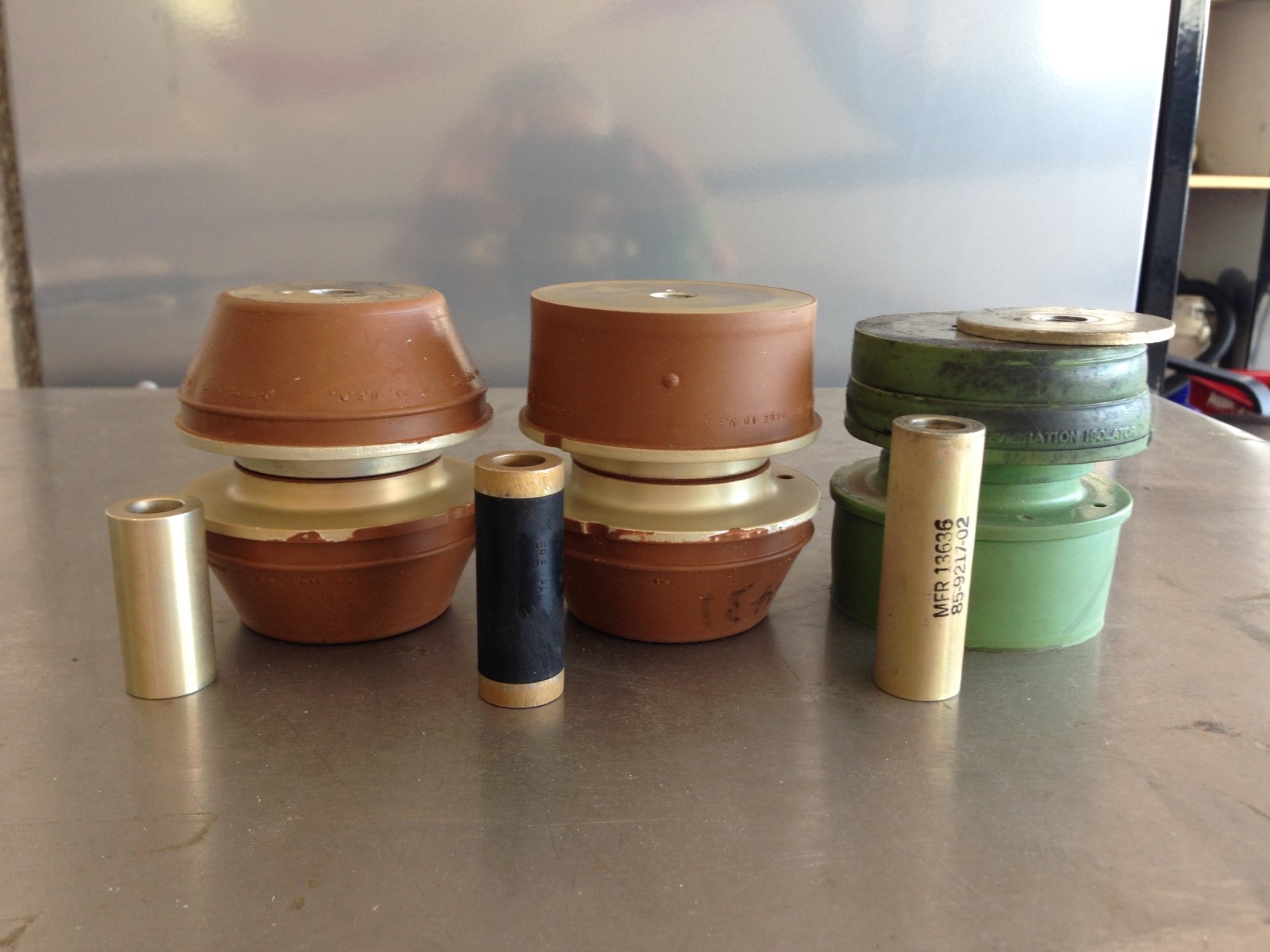
Rather than go with my gut, I emailed LORD technical support to make sure I was installing them the right way. It’s a good thing I did! There’s more to the mounting orientation than meets the eye. The new LORD mounts (clay colored) are approximately the same height as the old Barry mount (green and black). The -76 mounts appear to be symmetrical top and bottom, while the -75 has one tapered side and one cylindrical side. Also, notice that the -75 spacer is longer. Intuitively, the cylindrical portion of the -75 appears to be stiffer, so common sense says it should go on top to support the weight of the engine.
Here is the guidance from LORD technical support:
It’s a bit of tricky installation to get all of the pieces in the right places.
The J9613-75 is used in the Left Front location. Within the mount, the straight-sided J9612-42 is installed in the top/inside position and the tapered J9612-43 is installed in the bottom/outside position.The J9613-76s are used in the Right Front and both Aft locations. Within the -76 assembly, the bonded components are different even though they both have tapered sides. *Look for the embossed marking on the rubber section to make sure you have the correct part number in the correct position.
For the two aft locations, install the J9612-44 in the bottom/outside position and the J9612-43 in the top/inside position.
For the right front location, install J9612-44 in the top/inside position and the J9612-43 in the bottom/outside position.
| Location | Assembly Number | Top/Inside Component Number |
Bottom/Outside Component Number |
| Lt Front | J-9613-75 | J-9612-42 | J-9612-43 |
| Rt Front | J-9613-76 | J-9612-44 | J-9612-43 |
| Lt Aft | J-9613-76 | J-9612-43 | J-9612-44 |
| Rt Aft | J-9613-76 | J-9612-43 | J-9612-44 |
| NOTE: Part numbers are embossed on the motor mounts, but the numbers are very difficult to read without magnification. | 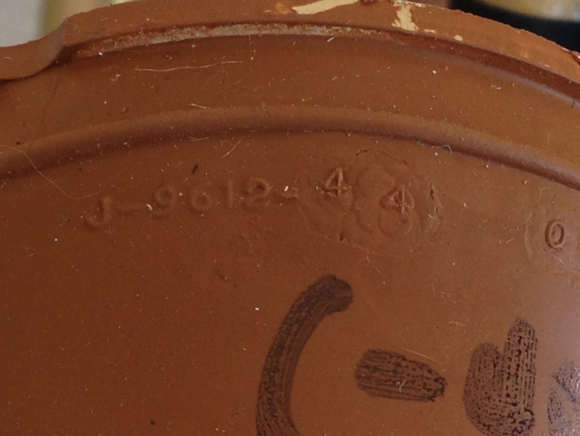 |
The Installation Process
NOTE: Click the images below to view full-zize. Click your browser's back button to return to the article.
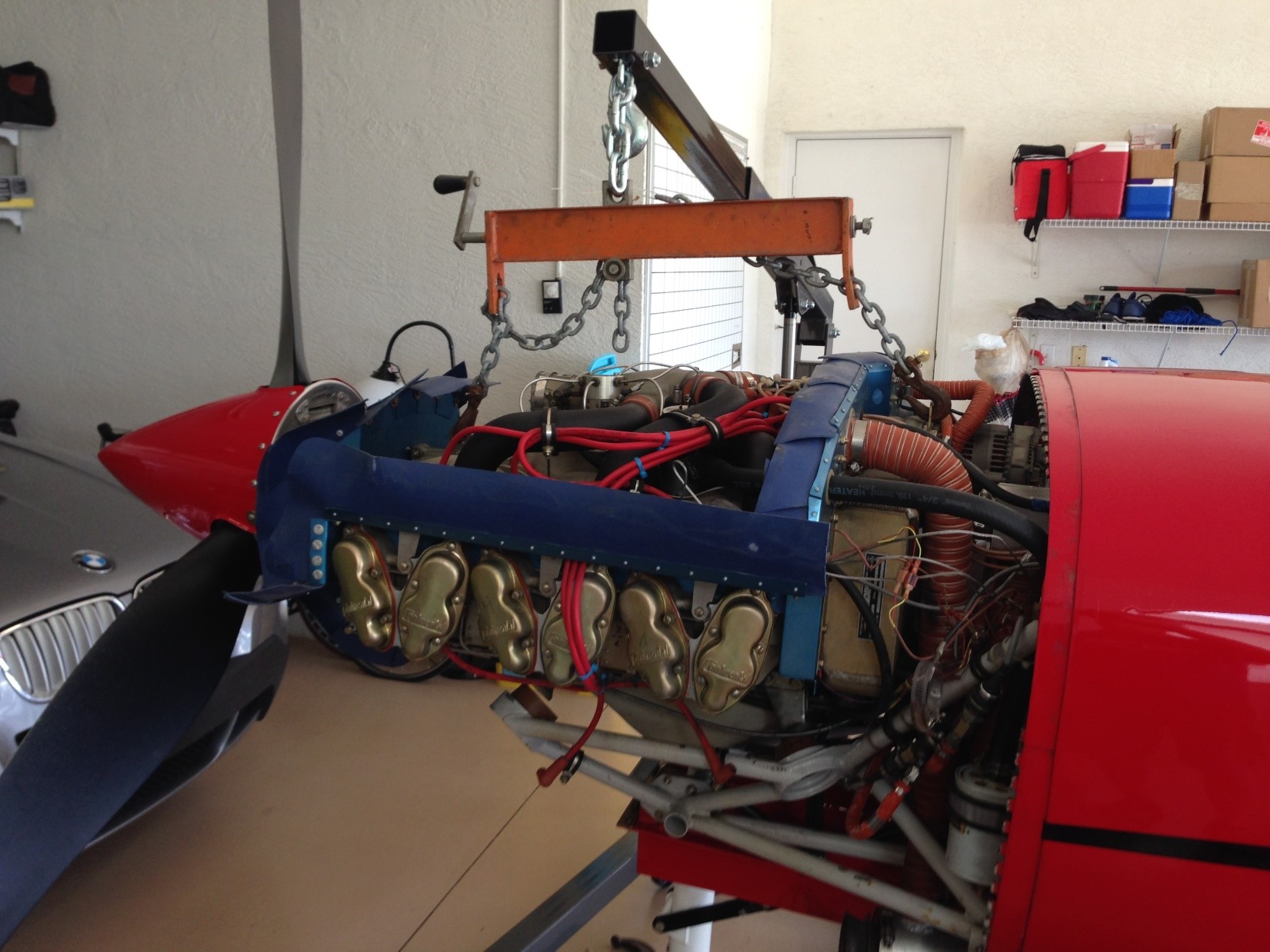
| Having installed the engine by myself many years ago, I had the notion that changing the motor mounts would simply be a matter of taking the weight off the mounts, removing four bolts, and installing the new mounts. Wrong! You have to raise the engine at least 1 ½” to get enough clearance to remove the old mounts. I had to remove the exhaust manifolds because they contacted the lower engine mount tube before the engine could be raised high enough. Removing the exhaust had the side benefit of improving access to the mounts. |  |
| Unlike the Barry mounts, the new mounts have a substantial amount of preload when installed. That means the rubber has to be compressed in order to line up the holes and get the bolts started. Because of the angled mounting rings, simply resting the engine on the mounts isn’t enough. In the photo at right note the aft mounts are aligned while the forward mounts are offset forward. |  |
| Since there was no way to have all four mounts aligned at the same time, I took the approach of getting the rear bolts started then pulling down on the prop to compress the front mounts. Trying to muscle the bolts into place really wasn’t an option. I used a cushioned pipe clamp with a socket acting as a spacer. The socket allowed me to get an open end wrench onto the bolt head while applying clamping force. The whole arrangement was a bit wobbly and I had to keep a firm hand on the pipe clamp to prevent it from slipping off. Fortunately, this is a relatively safe procedure because if the clamp does slip off the engine already supported so it isn’t going to fall or cause any damage. |  |
| The beauty of this method is that the bolt, spacer, and upper and lower halves of the isolator don’t have to be perfectly aligned before you start. As you tighten the clamp and turn the bolt, you will feel the parts pull into alignment and the bolt will drop into place with no risk of cross-threading. The LORD drawings recommend tightening the motor mounts to 450-500 in-lbs. The Legacy builder’s manual recommends installing locking tabs p/n 588-02 to prevent the motor mounts bolts from loosening. I installed Adel clamps at strategic points on the motor mount tubes to act as anchors for the safety wire. The bolts themselves move considerably as the engine shakes, so you must leave slack in the safety wire. The locking tabs are available from Lancair. |  |
|
For lifting, I used a Harbor Freight engine hoist and a load leveler. The load leveler has a single support point that rides on a jack screw. Moving the jack screw fore and aft changes the balance point, tilting the engine up or down. This is very helpful when trying to get the mounts lined up. NOTE: Don't forget to support the tail of the aircraft when you lift the engine off the mounts! |
|
The Results
The difference in vibration is like night and day. Before the change, the vibration at takeoff power was so severe that I would reduce to climb power (25” and 2500RPM) at 500’AGL and perform the big mixture pull early in the climb because vibration intensity was proportional to engine power output. Now the engine is actually smoothest at 2700RPM, with vibration increasing slightly as RPM decreases. Before, in cruise flight, the stick would vibrate side to side nearly an inch. I was always trying to find an RPM between 2300 and 2500 that provided the least objectionable amount of shaking. Now, the stick barely moves and there is little to no vibration coming through the cabin sidewall.
This was a bigger project than I expected, but I’m very pleased with the results. The reduction in vibration should increase the longevity and reliability of every component in the plane—flight controls, wiring, and all moving and non-moving parts. The comfort level is higher and the cabin noise level is lower. Many thanks to Bob Pastusek and Steve Colwell for paving the way on this.
For questions/comments on this post contact Adam via email: a.molny [at] lancairowners.com.