
The nose gear on your aircraft is a fairly simple component, but nonetheless critical to safe operations. This article includes recommendations for nose gear installation and continuing maintenance.
Installation
The nose gear is supported by two bearing blocks that are custom drilled during the construction process. Moving the blocks vertically relative to each other swings the gear left to right while hanging extended. Moving the blocks fore and aft relative to each other move the gear leg left to right in the retracted position. This alignment is very important to keep the gear in the same plane as the over center link. If not in alignment with the link throughout the gear swing, a side load on the links will be present. This promotes uneven wear and inhibits the emergency free fall due to friction. Checking proper alignment can be done by disconnecting the hydraulic cylinder and gas strut and removing the bolt holding the over-center link to the nose strut. The over center link should swing freely in between the two tabs on the nose gear with the gear held in any position from fully extended to fully retracted. If the over-center link will not swing freely between the tabs, the bearing blocks are not properly aligned. 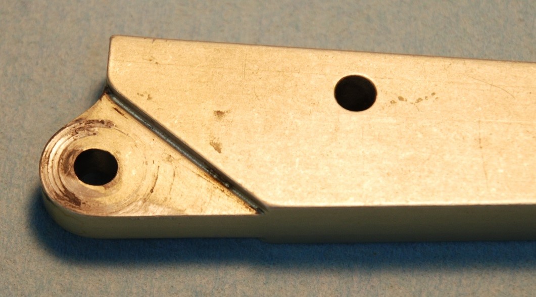 AN174 (close tolerance) series bolts are better suited for use in these joints than standard AN4 bolts. They provide less play and better bearing surface. Note that the shank of the bolt is the bearing in these joints. The bolt needs sufficient length so that the links are fully positioned on the shank of the bolt.
Bearing End Play
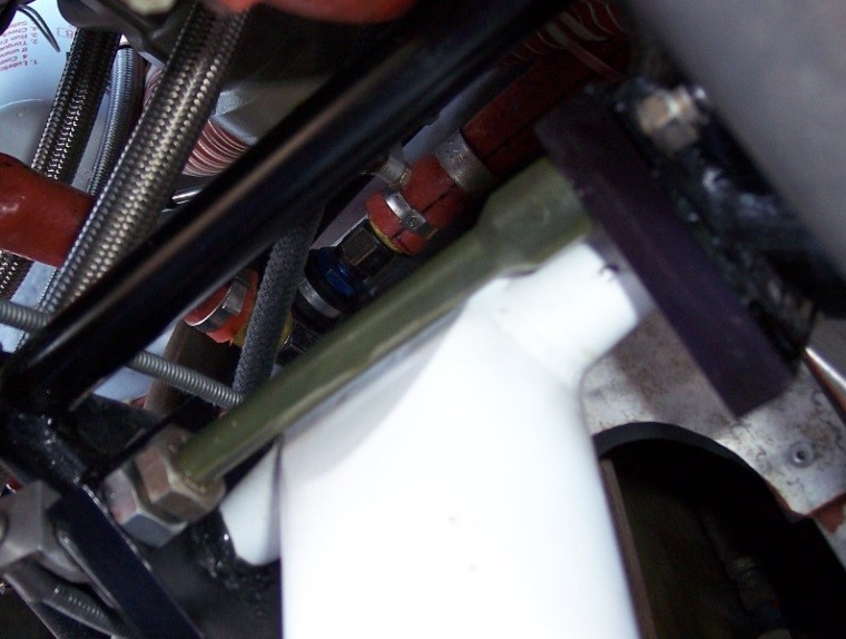 Most nose gear maintenance is done in an effort to avoid shimmy of the gear. To this end, it is critical during maintenance and condition inspections to look for play in the assembly. For example: End play in the main pivot bearings that allows side-to-side movement of the strut assembly. When properly adjusted there is no side to side play in the spherical bearings. The spacer in front of the strut keeps the bearing blocks separated. The length of this spacer determines what, if any, play is present in the bearings. Its length is adjusted accordingly. If the spacer is too short, excessive friction be present. Friction will interfere with the emergency gear extension. The original design uses a steel tube as a spacer between the bearing blocks. When the long ¼” bolt is tightened, it should take up all the end play just as it reached full torque. Finding the correct adjustment is a delicate task. I converted to an adjustable spacer to make this task easier.
Nose Strut Flange Brace
The flange at the base of the strut is held in by Loctite retaining compound. When applied correctly and in good condition, this material can easily resist 1000 ft-lb of torque between the flange and the strut. The condition of the Loctite bond cannot be inspected however and it has been shown to deteriorate over time. Also, some struts have been reassembled with thread-locker instead of retaining compound and will break free at much lower torque values. Many years ago Lancair came out with a secondary brace to re-enforce the flange to strut interface. The current model is a two piece design that is a bolt-on part. The brace will support the Loctite bond and ensure integrity of the joint both during normal use and in the event of a shimmy.
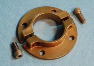 Newer two piece brace.
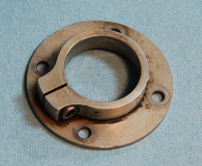 Older one-piece brace.
Bearing Preload
The nose wheel bearings should installed with some preload. This takes out the free-play in the bearing when under load and is a guard against shimmy and premature bearing wear. The preload can be checked by spinning the wheel. It should stop in less than one revolution.
The Free Fall Test
The free fall test verifies that the landing gear can be lowered and locked into place without any hydraulic pressure. This test must be performed in flight to ensure the gear will extend in an emergency, as it must extend against an air load. The nose gear is particularly critical in this regard. It relies on a charged gas strut to push out against the airflow to lock the over center link. An actual emergency extension should be done at a low airspeed to reduce the resistance on the nose gear (87 KIAS). However, to check the health of the system a free-fall at a much greater speed should be performed. 120 KIAS is a good starting value. If the gear does not lock into place, begin reducing speed until it does. Note this speed for comparison with subsequent test result. The trend will show decreasing airspeed required to lock the gear as the air strut loses pressure over time. Note that this test is more severe than an actual freefall in that the gear no longer has any momentum to help it extend into the locked position. On my 360, a fresh strut with 100 lbs of push will lock my nose gear at 120 KIAS.
Shimmy Damper Test
 The shimmy damper is a vertical piston inside the front of the strut. The piston is held in place by the two safety wired bolts located on the front of the strut. When the damper is functioning properly it provides a large damping torque that resist rotation. When cold the resistance is roughly xxx ftlb-secs. Movement from stop to stop should be smooth and seamless. Force reversal should not reveal a dead band. Nose struts with self-centering require the strut to be compressed at least one inch to check the shimmy damper. Non self-centering struts can be checked with the strut fully extended with the wheel lifted off the ground, but both types will be easier to test if you to deflate the strut first. It needs to be reinflated with up to 300 PSI of dry nitrogen when testing is completed.
Check For Internal Leaks
The interior of the nose gear strut should remain dry. There two small O-rings in the guide key retainer of the strut that isolate the pressurized interior of the strut from the inside of the tube. The only way to check for internal leaks into the interior of the strut tube is to remove the nose gear fork. If a large leak is present oil will come flowing out over the fork as soon as the fork is loosened. With the fork removed check the interior of the strut. It should be completely dry.
Check Fluid Level
The internal fluid level should be checked annually. To do this, remove the valve and fully compress the strut. Top off the strut with 20 weight fork oil with the strut fully compressed. Re-install the valve and charge the strut with ~200-300 psi of dry nitrogen through the filler adapter. You can compress the valve stem momentarily to relieve pressure so as to set the strut extension to approximately 3/4 of it's full extension with weight on the strut/wheel. This takes a fine touch--you may need to refill the strut a couple of times to get this right.
Conclusion
Following these guidelines should ensure you receive years of trouble-free service from you nose gear.