by robert pastusek
NOTE: The information and recommendations in this post apply to all retractable-gear Lancairs except the 200 series and the Evolution.
Investigation into the cause of an uncommanded nose gear retraction in Lancair IV-P N18AK following a normal landing indicated abnormal wear in the scissors link over-center pivot joints. The subject parts are referred to as the upper (one part) and lower (two parts) drag links in the Lancair build manuals. When functioning as designed, these two parts provide an "over center" feature that absorbs the shock load of the nose gear trying to move aft at touchdown. The abnormal wear noted in the drag links of the accident aircraft defeated the over-center feature, allowing the gear to retract when the nose wheel touched the runway.
Lancair modified the left and right lower drag links in approximately 2006 to include a bronze bushing where each attaches to the upper drag link. These parts were provided in later IV and Legacy kits, and as replacements for older parts in some cases. These new parts were installed incorrectly in N18AK, causing them to wear excessively to the point of failure after fewer than 100 landings. Subsequent examination of the defective components indicated a poor design of the original scissors linkage that contributed to excessive wear by allowing the midpoint pivot bolts (2) to operate with a side load rather than in shear.
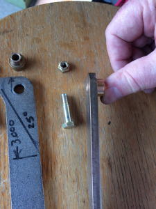
We recommend all owners of retractable-gear 300-series, IV-series and Legacy aircraft visually inspect the drag link (scissors) assembly as follows. With reference to the Figure 1, determine if the aircraft is equipped with original or modified lower drag links. The original upper and lower drag links were joined by two bolts with castle nuts, with the interface between the drag link and the bolts providing the pivot point. Modified lower drag links were drilled to accept a close-fit bronze bushing to replace the bolt as the pivot point. The bronze bushings must be securely bolted to the upper drag link so the pivot point becomes the interface between the bushing and the lower drag link, but we could find no written documentation of this changed assembly proceedure. Note in Figure 1 the bushing protrudes slightly from the lower link. This allows the use of a tension bolt and locking nut to securely clamp the upper and lower links while allowing rotation of the part.
Inspection Recommendation
After inspecting a small sample of Lancair IV aircraft LOBO has concluded that normal wear at the pivot between the upper and lower drag links will eventually render the over-center feature ineffective on both the old and new-design drag links. My N437RP, equipped with original drag links, has accumulated more than 2500 landings without enough wear to defeat the safety mechanism--but I estimate it will fail within the next 500 landings based on measured wear. On N18AK however, the newer links, modified with bronze bushings, were improperly installed with drilled bolts/castle nuts and not torqued. The resulting increase in wear defeated the over-center mechanism in fewer than 100 landings.
Based on that finding, LOBO recommends all owners of Lancair 300 series, Legacy RG and IV aircraft inspect their aircraft prior to the next flight as outlined below.
Inspection Procedure
- Visually inspect the drag links to determine if the aircraft is equipped with the original or modified lower drag links. If your aircraft is equipped with the original steel-on-steel drag links complete this procedure not later than your next condition inspection.
- For newer, modified drag links (employing bronze bushings) ensure the two bolts connecting the lower and upper drag links are fastened with self-locking steel nuts instead of drilled bolts with castle nuts (see Figure 2 below). If your drag links employ the correct tension bolts and locking nuts, and meet the torque specification below, complete this procedure not later than your next condition inspection. If you have the newer, modified drag links AND they are installed with drilled bolts and castle nuts you should complete this procedure prior to the next flight, preferably prior to moving the aircraft.
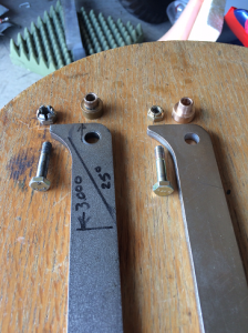 New drag link with correct fastener (bolt/lock nut) on right. |
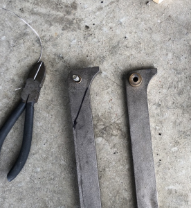 Failed drag link used drilled bolt with castle nut. Note excessive wear between bushing/bolt. |
| FIGURE 2 | |
- Support the aircraft so as to lift the nose wheel off the ground.
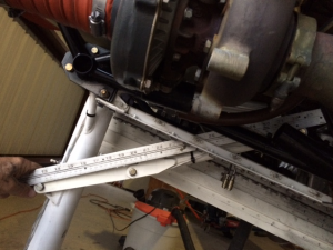
- Using a straightedge, check that the drag links are over-center per Figure 3. The length of movement beyond over center is not specified in the assembly manual, but airplanes in our test ranged from ¼" to ½" as measured from the centerline of the pivot bolt joining the upper and lower links. More is not better because it excessively loads the steel stops between the drag links.
- With the hydraulic pressure zeroed, remove the emergency extension gas spring. This is easier if you first remove the long bolt connecting the nose strut to the lower drag links per the Lancair assembly manual instructions.
- With the gas spring disconnected and the nose wheel off the ground, apply fore/aft force to the nose wheel and observe any movement of the pivot point between the upper and lower drag links (see video below).
- Any amount of wear in the pivot joints between the drag links will cause the joint to move when fore/aft pressure is applied to the nose wheel because the steel-on-steel contact point between the ears of the lower drag links and the upper link acts as the initial pivot point for the assembly. If wear in the joint is sufficient to allow it to move over-center as measured in Step 4, the nose gear is restrained from retracting at touchdown only by the combined hydraulic and gas spring pressure. If either fails, it's likely the nose gear will retract upon a normal touchdown.
Inspection Criteria
The bolt with castle nut used to secure original-style drag links should have enough free play to turn easily with a wrench, but no more. The newer, modified links with bushings MUST be installed with a tension bolt at the pivot joint that is torqued to 90-100 inch/pounds. It is not acceptable for the tension bolt used to secure newer-style drag links to turn with less than the specified torque applied. If you have the new type drag link, the attachment bolts must be inspected and re-torqued at each condition inspection. If you have the old-style links without bushings, the pivot bolt castle nuts should be adjusted to allow the bolts to pivot freely with minimum play.
Corrective Action
If the above test indicates the drag link pivot point moves past or even close to the over-center position, the drag link assembly must be replaced or refurbished. Once this joint develops free play, the wear rate will increase exponentially rendering the over-center mechanism ineffective.
Replacement parts are available from Lancair Inc. and are cheap insurance against a very costly landing incident. In most cases, we recommend replacement of the two lower drag links and correct installation of the new parts with tension bolts between the upper and lower links. Replace the upper drag link if the holes have been worn to the extent the new bushings can't be mated and torqued securely to the upper link. Note that this part has been upgraded to a stronger part by SB074-0111, 01/06/2012. If you have not complied with SB074-0111, 01/06/2012 now is a good time to do so.
One observation we made in 2017 was that these pivot points would function better and last much longer if they were designed as forks with a pivoting blade between supporting sides. This would allow the pivot bolt to work in shear rather than being twisted by the force of nose wheel at touchdown. While this pivot point must be fastened loosely enough to pivot freely, any free play in the joint exacerbates the rapid elongation of the pivot holes with the current design. A couple of folks have offered to make these, or similar replacement parts. We'll keep you posted if they are made available for purchase. (NOTE: The Lancair Corporation-Uvalde made such replacement lower drag links available via SB077-0518 in 2018 and updated it via SB077-1022. Also, I have developed two alternatives to incorporation of Lancair SB077 that provide alternative methods of replacing the unacceptable bronze bushings.)
For further nose gear maintenance information, including a regular inspection regimen, see Chris Zavatson's article: HERE
For questions/comments on this post contact Bob via email at r.pastusek [at] lancairowners.com.
Updated: 2/2024

